Author: Marek Olejnik– Senior Embedded Software Engineer at Blue Chip Technology
1. Introduction.
Electronic systems for industrial applications often need a human interaction. The user interface was historically implemented on a physical control panel comprised of buttons knobs and indicators. Modern systems can use virtual user interface presented on a touch enabled LCD screen where physical buttons and indicators are replaced by their on-screen counterparts.
Advantages of virtual control panels are numerous: reduced failure rate of mechanical parts (button wear out, dirt ingress etc.), flexibility during control panel design, reduced space constraints, costs of servicing, reusability of such control panel in different projects and others. Production of a virtual control panel can be a daunting task, depending on the skills of the software development team and the tools and libraries they have available.
In this article I’ll take a look at how SquareLine Studio can be used to simplify the design and production of a virtual control panel run-on Blue-Chip Technology’s modular Touch screen HMI range, BETA. In this instance we will use a TM3 SoM paired with a HB8 and a 7” LCD with capacitive touch. We’ll then integrate the UI with code to control and animate a 3m LED string via the system’s SPI interface’s MOSI line which is accesses via the 50 way expansion header available on all BETA products. The Buildroot Linux root file system can boot to the application in about 6 seconds, which can be further optimised depending on the options selected when creating the Buildroot rootfs.
2. UI Designer tool
SquareLine Studio (SLS) is PC based tool that enables design of a user interface (UI) of bespoke control panels in a form of computers screens that can be linked together in a desired workflow. SLS actually sits on top of the open source LVGL graphics library.
The main advantages of using SLS are:
- The whole UI design of the embedded application can be done in one tool by a graphics/UI designer person. A software engineer is generally not required in this stage.
- It generates the application source code for the whole UI part of the application. That means all buttons, sliders, switches and indicators will be functional (in terms of visual appearance) once the so
- urce code is exported. There are 2 options for the source code type, one is C code, the other is a Micro Python code. The source code generator embeds the graphical resources into the UI library therefore they are part of the application itself. This not only simplifies the resource loading but also ensures all required resource files are always available to the control panel application.
- There is a visual preview of the whole user interface where the designer can test the operation of the individual UI elements and check the transitions between the screens.
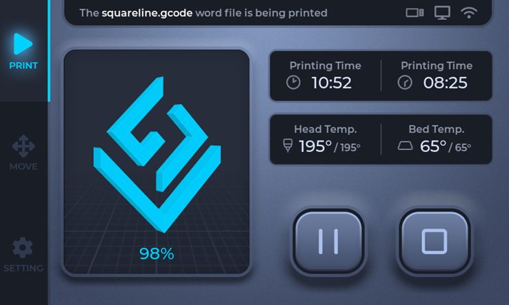
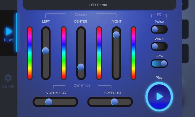
I used an evaluation version of SLS to demonstrate the ability to produce a basic control panel to interactively drive an addressable LED string from within the TM3 Beta System. I used the SquareLine’s 3D printer example as a starting point, which has the main menu on the left part of the screen and control elements in the central part of the screen.
The design process itself is similar to other content creation tools, where the screen elements are represented in a hierarchical tree structure and the properties of the screen elements can be modified in a property panel. The layout editing system is intuitive and I did not need to consult the online help reference during the whole design time which took about 2 days including the preparation of graphical resources. I often checked other demo projects that come with the SLS to figure out how certain UI elements are configured because each element has numerous properties that affect its visual representation – from background image, border style, shadow style, padding etc. Tweaking the properties in the editor changes the visual representation of the elements instantly and to examine more complex UI elements there is an interactive Play mode available.
3. The event system
When the UI design is finished and before the source code for the application is exported the UI events need to be defined. The UI events link visual actions – like a press of a button – to functions that will be called when the action happens. The definition of UI events is done in the SLS and each visual element can enable one or more events. Several types of events can be defined, but I opted for calls of event functions. For example, when a switch is turned On or Off, then a code function is called. Similarly, when a slider is moved then another code function is called. All the events functions are generated by SLS based on function names provided in the element properties. A nice feature of SLS is that it recognises whether a called function was already implemented and if so, it preserves such implementation during next code export.
4. Embedded application
To produce the application with the custom control panel the UI design needs to be exported from SLS in the form of C source code. This is done by clicking a menu item in SLS. The code export itself is instantaneous and it remembers the last path where the code was generated. The generated UI code utilises LVGL graphics library to render the UI elements on the screen. The LVGL library has a small footprint and was designed to run on variety of back-ends like SDL and Linux frame buffer.
The list of software components needed to produce the final application is as follows:
- UI code: generated by SLS by exporting the design to a C code
- LVGL library (source code provided with SLS)
- graphical backed for LVGL (source code provided with SLS)
- event function implementation – written by a software engineer
The starting point of the application – typically the ‘main()’ function – is implemented in the LVGL backed, so the custom initialisation code of the ‘invisible’ part of the application (like network communication, peripheral initialisation etc.) can be implemented in a callback function of the very first screen. A good practice is to service the peripherals in its own thread so that the UI processing is not blocked. Also, the implementation of the event callback functions should be minimal and non-blocking to ensure that the UI experience is smooth and without visual hiccups.
The full source code of the LED Demo application can be found on the following link:
GitHub: TM3 Squareline Studio LED Demo
Let’s take a look at the source code structure. The code exported from SLS is in the ‘led_demo’ subdirectory, LVGL library source code is in the ‘lvgl’ subdirectory and there are 2 graphical backends ‘app_sdl’ and ‘app_fb’ subdirectories. The code that controls the addressable LED strip resides in ‘led_demo/led.c’ code. The SDL graphical back-end is actually not needed, but it is provided as a debug option that can run the whole application on the PC – or at least the UI part, depending on peripherals. The FB graphical back-end is used to produce an application that can run on the target HMI unit – as I mentioned earlier, I used Blue Chip Technology Beta HMI system based on TM3 module. The code repository has 2 build scripts, one for each graphical backend. Note that the ‘build_app_fb_arm.sh’ build script has a TOOLCHAIN variable that specifies the path to a GCC compiler. The compiler for this demo was produced by Buildroot system during compilation of Buildroot_QT5 demo as described in Linux for TM3 document provided by Blue Chip Technology. The demo application build scripts can accept 2 parameters. The ‘clean’ parameter cleans the build directory so that the application is built from scratch. The ‘run’ parameter starts the application after the build. The ‘build_app_fb_arm.sh’ build script is able to copy the application to the target Beta unit over network (via scp) and run it remotely (via ssh). The LVGL, and the generated UI code use ‘cmake’ build system which is called from within the build scripts.
The event function implementation resides in ‘led_demo/ui_events.c’ which is generated by SLS. If you check the source code in the ui_events.c file, you’d see that the implementation is quite minimalistic, and the event functions are bare wrappers that simply call appropriate LED functions. Such code structure ensures clean separation between the UI code and the code controlling the LEDs or other peripherals.
The LED driving code can control a LED strip based on the ubiquitous WS2812B LED IC. The physical interface for driving the LEDs uses single data line and no clock line. For that reason, the communication protocol is quite time sensitive. To generate a stable pulse train, I used an SPI interface’s MOSI line where the length of the pulses is defined by the bit pattern sent to the SPI device. Special attention was needed for the voltage level of the data line as the 3.3V produced by the Beta unit was slightly below the LED’s VIH specification (0.7 * 5V). That was solved by a high-speed level shifter IC because the slow level shifters based on a single Mosfet were not able to switch the data levels quickly enough. The switching frequency the level shifter has to support is at least 1MHz. When the level shifter is not up to the task the LED strip produces visual artefacts and glitches. Changing the colours on the LED strip involves opening the SPI device file exposed by the ‘spidev’ Linux kernel driver and then writing the stream of data representing the RGB values of individual LEDs to the device file.
5. Using SLS and the demo code in your project
Producing your own application with custom control panel design should be straightforward. You can use the source code of the LED demo as the starting point. Ensure you can compile it and run either on the PC (when compiled by the ‘./build_app_sdl.sh run’ build script) or to run in on TM3 Beta unit (use build_app_fb_arm.sh build script). Once that is working for you, either use one of the SLS example project (like a 3D Printer example) or try to design your own control panel screen. For start, make sure the screen resolution is 800×480 pixels as that is the screen size currently used by the build scripts. SLS will let you choose which hardware board you want to design the UI for when you create a new project. Select the Eclipse SDK board which is compatible with the LED demo code. The SLS project screen resolution should match the physical resolution of the screen on the Beta unit. If you need a different resolution for your project then adjust the screen resolution variables in SLS and then modify the application build scripts, specifically variables __UI_PROJECT_HOR_RES__ and __UI_PROJECT_VER_RES__. When exporting the UI C code of your new project, select either the ‘led_demo’ directory (which will overwrite the current LED demo UI) or use a new directory on the same level as ‘led_demo’. If you chose to create a new UI project directory for the exported code, then ensure the variable PROJECT is set to the name of that directory in the build scripts. Also, modify PROJECT_SRC variable which lists additional source code files needed for the app to function. In the initial stages of the development of your application the extra code won’t exist, so you can keep that variable empty. Later, when the UI part of the application is complete set the variable to contain a list of the C source code files that implement the non-UI functionality of the application. The ‘run’ parameter of the ‘build_app_fb_arm.sh’ lets you to upload an run the complied application on the Beta unit. If you want to use such option, make sure the IP address at the end of the build script matches the IP address of the Beta HMI unit.
6. Conclusion
Writing an embedded application with customised user interface can be a non-trivial task. There are a wide variety of tools available which aim to simplify the process.
The SquareLine Studio provides a powerful tool to enable the application screens and its resources to be produced and managed and then to be exported as a compact code component that the main application code can be easily integrated with.
With the source code provided you can jump-start embedded application prototypes on Blue Chip Technology Beta HMI units and have them ready in a matter of weeks rather than months.
About Blue Chip Technology
At Blue Chip Technology (BCT) we specialise in design and manufacture of embedded electronics systems, Hardware, Firmware and Applications. Our typical customer will usually have a proof of concept and will work with Blue Chip to engineer what is often a complex collection of circuit boards into a commercialised solution.
The Beta HMI platform offers an opportunity to develop those prototypes with a validated, field proven integrated SBC, LCD and touch platform, saving several design and development iterations. BCT’s in house manufacturing and commitment to full life cycle support offers a unique proposition to dramatically reduce time to market, approvals and start-up costs.
www.bluechiptechnology.com sales@bluechiptechnology.com